
DIY 18U, 104HP Eurorack Case (part 1)
NOTICE: I am not a woodworker, cabinet maker, carpenter, etc. There are probably way better ways to do what I’ve done here.
Literally anyone is better at this than I am.
This means you.
I am just someone with a vision and the motivation to see that idea brought into reality.
I remember back in the late 90’s seeing rumblings on the internet about a modular synthesizer format that was gaining a lot of attention— Doepfer’s system 100 and its modules. I continued to follow the evolution and progress of the so-called ‘eurorack’ stuff throughout the 21st century, but never could justify the spend, not only on all of the modules you’d need to have a minimally functional system, but also a suitable enclosure, power supplies, etc. No matter how I looked at it, there was a high cost of admission into what was basically a reinvention of modular analog synth architecture. I knew software synths we getting better and better, and they took up no more space in my studio than I had afforded to my DAW host and controllers.
Eventually, I decided that it was time to have a true analog modular synth for my mini conservatory and with my positive experiences with the Behringer PolyD and BARP 2600, I decided to try the Behringer Eurorack interpretations of Roland’s System 100.
The Boland 100 modules were really affordable and had a really pleasing layout and overall look and feel, so I began designing a system that would use all of them and soon learned about things like HP (horizontal pitch, 0.2”) and the +12V and -12V loads and such that needed to go into proper Eurorack planning.
I came up with a 6U, 104HP cabinet that would house the entire Boland 100 and an 8HP Doepfer MIDI-to-CV interface.
I scoured the ‘net for the best deals on rack rails, power supplies, etc. and decided to just order some stuff and later commit to making something to house all of it.
I knew I’d want to expand the system (that’s the best feature of modular— expansion possibilities), so I ordered 12U (twice what the Boland needed) of rails at 104HP. I settled on 104 based on the limited available horizontal room I had for this project.
I got my first order of rails from Synthrotek. They were missing half of the threaded inserts. I reached out to Synthrotek via email and explained my predicament, and waited to hear back. While I waited, I decided to hedge my bets and order another 6U of 104HP rails from ModularSynthLab in Netherlands along with an MSL power kit with 6 distribution blocks and 3 power supplies.
Synthrotek got back to me in about 2 days, admitted the error on their part, and immediately express-shipped the missing items (plus a few bonus gizmos for my trouble), and that response has made me a repeat customer with them ever since.
The MSL stuff is all a pretty good value as well, so now I had enough rails to make a (to me) monster 18U, 104HP Eurorack mega-case.
Of course just knowing how tall (18U) and how wide (104HP) isn’t enough to fully realize a functional, attractive case worthy of the thousands of dollars of electronics it would eventually house, so I began scouring the internet, looking for ideas.
I saw some cases made from antique crates and furniture— a neat idea with a lot of potential charm for sure— but if I went that route, I’d have to find antique items that I wouldn’t feel bad about gutting/defacing, and they’d have to exactly fit the limited space I have; probably a tall order.
A lot of cool, all-metal shells came up, and they had a lot of appeal since they were way thinner than anything made of wood, but I’d have to hammer-form stuff or make it out of plates, angles, rivets, screws, etc., so I kept looking for better options that seemed do-able (to me, with no real skills or fancy tools like bead rollers, brakes, punch presses, etc. to make it not look like crap when done.)
Since the thing was bound now to be pretty big, and it would sit at eye level, I decided that wood was the best material as I knew I could make it look good enough that eyes would focus less on the case and more on what sat inside.
There are a lot of great pre-made cases out there on the market sites like Etsy and others. They also cost a lot of money. After building my own from scratch, sourcing the wood, hardware, power supplies, wiring, etc., I can say with some authority that those cases cost what they do for a reason— there’s a lot of careful work that goes into things like these, and the profit margin for people who make and sell them must be pretty thin given the number of hours mandatory for even a small, quality case build. If you have more money than time, I think buying one of the many terrific cases out there on the market is an excellent idea. If you already bought most of your hardware and only need a box to mount it into, then you have to play the hand you dealt yourself. And that I did.
I decided that this unit would be used standing or sitting because of its vertical nature, so I tried to optimize the angle of each 3U rack assembly to work from a low or high vantage. I went with 30 degrees (from vertical) for the lowest row, 20 degrees for the next one up, vertical for the next three and finally -20 degrees for the top. After having committed to those, I drew the thing in CAD, inlaid little templates for the rack side-brackets to get the dimensions of the cheeks right, and then plotted in the other dimensions based on Eurorack standards for depth.
I used a square, some cardboard, coordinates from the drawing, and a straight edge and pencil to connect those coordinate points to create a cardboard profile template of the cheek piece profile. I cut along the profile with a razor knife and saw for the first time just how tall this thing was going to truly be…

Eager to see if that I got all of my dimensions correct, I staged the Eurorack rail assemblies onto the cardboard…
Umm… how did I get that perfect? I guess being careful with measurements and layout really does pay off.

Really satisfied with the template and my measurements/proportions, I decided to go straight into wood. I split the 48” panel down the middle so I could make my two sides simultaneously with single cuts to ensure the best-possible uniformity.

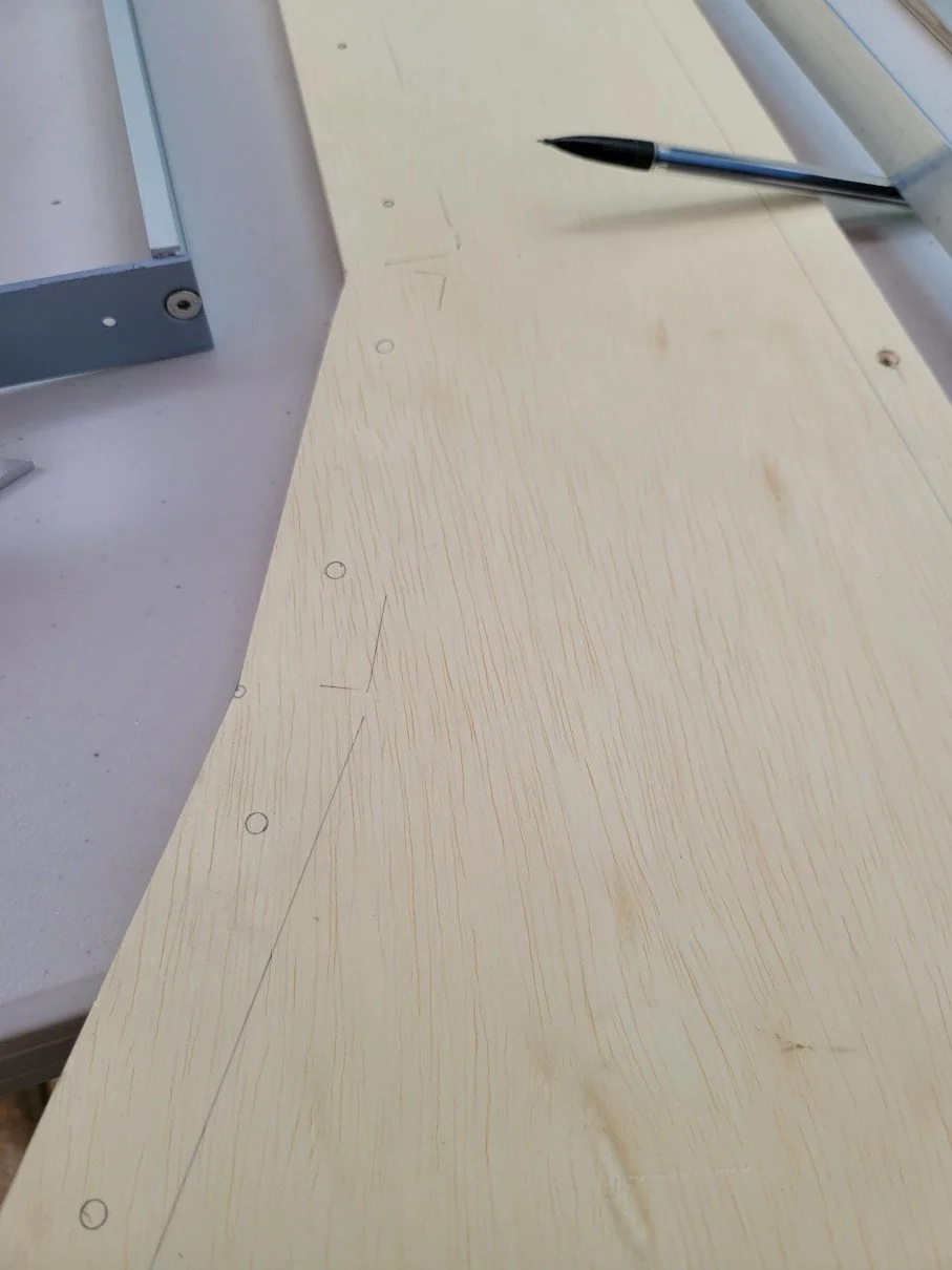
I laid the pieces together, plotted my points, and connected them with lines to establish the guiding profile on the wood. I made some tweaks to the top and bottom as I decided the angle of the top needed lid clearance if I ever put a deep module up there, and the bottom needed to be an inch taller to best accommodate the height of a tall controller.
I used my cardboard template to check that everything else was where it needed to be.
I also marked on the top, bottom, and back edges what would help me find the centerline for dowel drilling in later steps.

No more fooling around. I committed to what I had drawn on the wood, fastened the two halves together with deck screws in some of the eventual dowel holes, and took it for a long, careful, difficult (inside curve/corner cuts can be a pain) trip against the bandsaw.

Bandsaws are not good at finishing cuts and leave a very wavy, rough edge, so I set to work with a belt sander at 80, and then 120 grit to get the lines straight and the inside corners sharp and accurate. I refined it further with a palm sander running 220 grit.

Flat enough according to my ruler…

This fret rocker says I have a little more flattening to do on this facet…

And my ruler shows I’m almost there with the bottom facet— just a little bit of daylight left.

Once I got the edges as flat as I thought they needed to be, I separated the halves by removing the deck screws and began again to mock-up and position the hardware. With both sides practically identical thanks to the Siamese cutting and finish sanding, I knew if I lined up the hardware on one side, it would reasonably line up with the other once assembled. (I doubted it would be that easy at the time, but when assembly time came, it really worked exactly as I had hoped.)


The back and bottom are just simple rectangles, but the top and bottom valences on the front need some specific geometry to look good. I set my circular saw’s guide to 30 degrees and make the cut for the bottom valence…

And wouldn’t you know it, but the casting on that saw guide and the pointer are pretty much dead-on. Penguin-san says it’s 30 degrees off from 90 and Penguin-san never lies.

The numbers work and the angles match. Now to get that front edge…

Practically no runout. I’ll take that. I’ve learned not to push my luck and accept near-perfect as a total win, and keep moving toward the goal— completion.

The bottom and back are just rectangles, so I didn’t need to do anything too fancy to get them on-dimension. With 4.25 sides of the shape ready to be joined, I used my already-drilled dowel pilot holes to glue, true, and screw the sides to the back, bottom, and bottom valence. The screws will clamp the surfaces until the glue dries. When I remove them, I will drill and dowel the spots where they were so that the sides of the cabinet will be smooth looking wood, uninterrupted by any hardware. I think this looks much nicer than screws or buttons. Again, this piece is big and it will be very visible to anyone in the room where it will stay. Looks really count on this project.

I just have to cut the top valence with that 20 degree angle on the top, and the lid will need a corresponding edge angle to butt against it.

I drilled some pilot holes for the dowels in the front valences…

And with the glue still drying, I took advantage of the time and began to clamp my rails into place to verify the layout and make any needed adjustments and then put in the final markings for both sides.

Time to commit and mount these rails to get their screw holes registered before I remove them one final time for finishing.

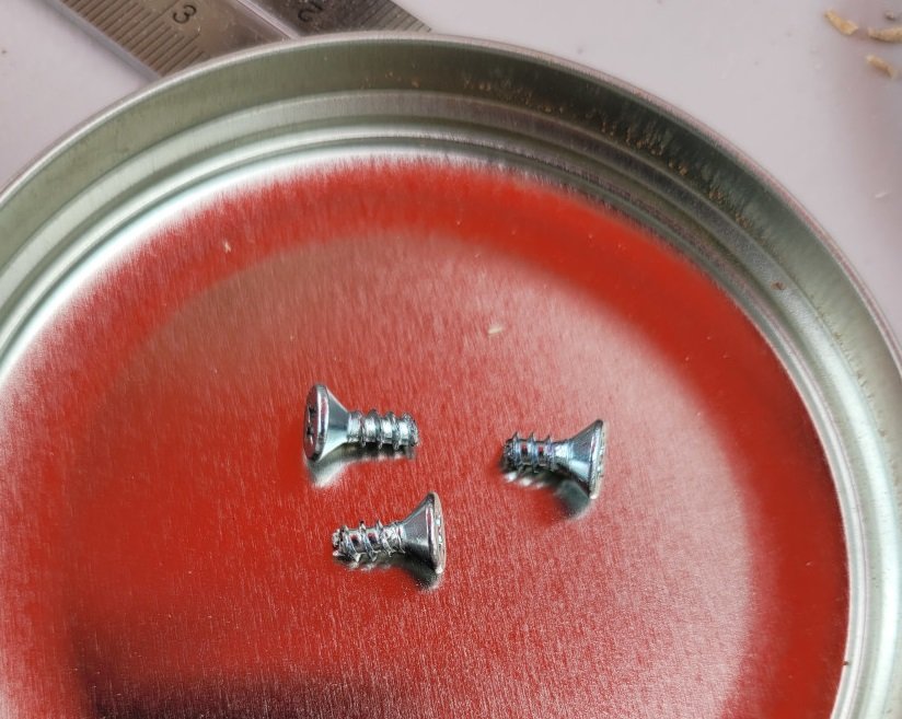
I went with 1/2” plywood for the sides, (3/4” would have meant and extra 1/2” of total width which I couldn’t spare in the space I had for this monstrosity) and I didn’t have any screws the appropriate length, so I used mini bolt cutters to trim them an dmake sure nothing poked through once seated.


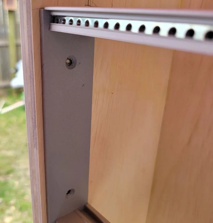
At this stage, I wanted to see how the modules would fit with the faceted planes…

I wasn’t sure if I needed a little extra space between the courses of rails with that angle, but even with the panels touching, there’s still more than enough latitude with the centers of the threaded holes being as far apart as they naturally are— the top one is about 1.5 mm down and the bottom is about 1 mm up from their respective hole centers in order for them to even touch on their edges.

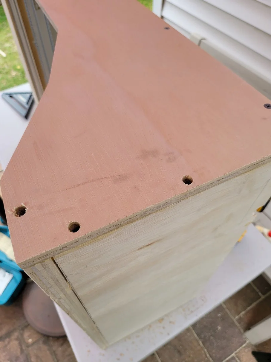
Drill, glue, dowel— everywhere…


Japanese razor saw cuts them flush like a champ…

That blowout (from drilling) on the top ply below that hole will probably disappear after sanding. If not, wood putty will do the trick well enough.
I’m not serving a formal dinner to visiting dignitaries on this thing— It’s a cabinet for working machinery.


While looking for my Forstner bit guide in my garage, I came across this. Could come in handy for a Russian vocabulary test? I believe they were less than $3.

And that concludes the construction of the cabinet. More in the next part.